Introduction to Metallographic for Powder Metallurgy 粉制金金相技術 (三)
接續四月刊
1.3Mounting鑲埋
Once the proper cross-section is removed from the part or test piece, it is usually encased in a plastic or polymer carrier mount for further processing. The mounting process offers several preparation advantages over preparing un-mounted samples. 一旦適當的橫截面被從零件或試件中取出,它通常是用 塑膠或聚合物載體鑲埋住的,以用於進一步的拋光加 工。比起未鑲埋的樣品,鑲埋提供了樣品準制的優勢。
The size and shape of the mounts makes handling and processing easier and more convenient, in addition to fitting standard configurations for automated or semi-automated preparation systems.
Furthermore, mounting helps to maintain the integrity of edges and intricate shapes, permits the preparation of small cross-sections or individual powder particles and strengthens and protects delicate or fragile sections. 鑲埋塊的大小和形狀使後續樣品備置處理更容易和更方 便,除了用於自動或半自動製備系統的標準配置之外, 鑲埋有助於保持樣品邊緣和復雜形狀的完整性,允許小的橫截面或什至是單個粉末顆粒的製備,並加強和保 護微細或脆弱的部分。 Three basic material categories are used for mounting. They are thermosetting, thermoplastic and castable. The thermosetting and thermoplastic groups require both pressure and elevated temperature to create the mount. Each material must be processed in a specific sequence of heating, cooling, and application of pressure. These must be followed to maximise the quality of the metallographic mount. 鑲埋塊的三種基本材料類別,它們是:熱固性、熱塑 性和灌注料。熱固性和熱塑性塑膠組需要兩個參數: 壓力和升高的溫度來完成鑲埋。每個材料必須在一個 特定的順序加熱,冷卻和壓力的應用。這些必須遵循, 以最大限度地提高金相鑲埋的品質。
Conversely, the castables are generally liquids that are used at room temperature, although the performance of some castable materials can be improved with elevated temperatures. The thermosetting are Bakelite (phenolics), epoxy powder, and diallyl phthalate and are available in the form of powders, granules, and pre-forms. Thermoplastics are acrylics such as polymethyl methacrylate (Lucite), usually available in powder form. Epoxys and some acrylics comprise the castable group and are usually used as two or three part liquid or liquid-solid systems. 相反,灌注料一般是液體且是在室溫下進行,儘管一 些灌注料的性能可以隨著溫度升高而提高。熱固性的 材料是以電木(酚醛樹脂)、環氧粉末、及鄰苯二甲酸 二烯丙酯有粉末、顆粒的形式,和類似的前驅物;熱 塑性丙烯酸樹脂如聚甲基丙烯酸甲酯(有機玻璃),通 常可用是採粉末狀。環氧樹脂和丙烯酸包括灌注料組 和通常作為兩或三部分純液體或液-固混合系統。
As a word of caution, since the thermosetting and thermoplastics require heat and pressure to form the mount, the increased temperature and pressure may have adverse effects on some of materials to be prepared. Some microstructures may be
changed by the heat required to create the mount and the increased pressures can cause physical distortion to fragile, thin, or delicate samples. 必須提出一個謹慎的注意字眼,由於熱固性和熱塑性 塑膠需要熱量和壓力來進行鑲埋過程,增加的溫度和 壓力可能對一些樣品備置有的不利影響,一些微觀結 構可能被改變來自鑲埋過程的熱量,以及鑲埋過程增 加的壓力可能會導致樣品表面物理性失真,尤其是脆 弱、薄、或微細的樣品。
The physical properties of each mounting material type are different and one type may be preferred over another in a given application. For example: 每個鑲埋材料類型的物理性能是不同的,個種類型都 具有各自的優勢。例如: ● Thermosetting mounts are generally harder than the other mounting material groups 熱固性鑲埋材料通常比其他鑲埋材料組硬度更高 ● Castable epoxy has adhesive qualities that may help retain small samples
灌注式環氧樹脂膠粘劑的品質,有助於保持細小樣品 的正確性 ● Thermoplastic mounts are generally clear, which may be beneficial where planar location is important. 熱塑性鑲埋材料一般是透明的,這可能是更有益於重 要的觀察平面設定。
1.3.1 Fillers and additives填料和助劑
Particulate fillers are often added to a mounting material to enhance specific mount properties. 顆粒填料往往被添加到鑲埋材料,以提高鑲埋塊的性 能。
Hard additives such as glass fibres, ceramic, or metallic particles are sometimes mixed into the base mounting powder or liquid to increase the overall mount hardness. This will help to maintain the planar surface of the mount and minimise the height difference between the mounting material and the sample during preparation.
硬質的添加劑,如玻璃纖維、陶瓷、或金屬顆粒有時 混合到鑲埋粉的基地粉末或液體中,以增加整體硬 度。這將有助於保持鑲埋材料的表面平整度,並儘量 減少鑲埋材料和样品在製備過程中的高度差。 (例如 觀察樣品是硬度很高的陶瓷或碳化物金屬)
In addition, electrically conductive powders such as copper and graphite are added to the mounting material to create conductive mounts for use in electron microscopy. The additives can cause difficulties in some situations by contaminating the surface to be analysed. In addition, the metallic additives can sometimes react with etchants or cleaning fluids and change the appearance of the samples. Further, the conductive mounting materials use additives the PM industry routinely uses in alloying ferrous powders. 此外,可導電粉末如銅和石墨被添加到安裝材料,以 作為用於電子顯微鏡觀察時的導電鑲埋件。有添加劑 可能污染樣品的表面進行,導致在某些情況下的分析 困難。
此外,金屬添加劑有時會與蝕刻劑或清洗液發生反 應,改變了樣品的表面形貌。因此,導電的鑲埋材料 使用添加劑,在粉末冶金工業經常使用的是合金化鐵 粉末以避免鏽蝕。
The possibility of erroneous information coming from the mounting material is real and should be recognized. 從鑲埋材料得到的錯誤資訊必須要被分辨出來。
1.3.2 Edge protection邊緣保護
A possible problem arising from the use of high shrinkage mounting material, or not allowing the mount to cool under pressure where required, can be a gap created between the sample edge and the mount. 有一個可能發生的問題,採用高收縮性的鑲埋材料或 是不允許鑲埋冷卻過程有壓力,這可能使被觀察樣品 邊緣和鑲埋塊之間隙的產生。
This condition often results in rounding of the sample edge and entrapment of liquids or abrasives in the gap. This is seen in P1-Fig.10 where the edges of two gear teeth are not in the same plane as the core of the teeth. The dark space at the edge of the teeth is the gap. It is obvious in these photomicrographs that any evaluation of the edges is questionable. The blue areas in P1-Fig.10a are stains produced by entrapped liquid from in the gap bleeding out onto the sample edge. These stains are not part of the microstructure and tend to disguise or hide the real microstructure. 通常這種情況導致樣品邊緣和封包的鑲埋液體或塑料 產生間隙,如P1-圖.10中,兩個齒輪的齒邊緣不在 同一平面內就如齒的核心部,牙齒邊緣的黑暗空間是 間隙。這些照片很明顯,邊緣的任何評價將是值得懷 疑的。 P1-圖.10(a)藍色區域是由於鑲埋液從間隙中 滲出到試樣邊緣產生污漬。這些污漬不是微觀結構的 一部分,但往往掩蓋或隱藏真實的微觀結構。
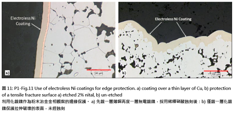
In situations where the sample edges are of primary interest and importance, surface coatings canbe applied as protection from rounding. One of the most effective is the use of electroless Ni coatings. P1-Fig.11 shows two uses of the electroless Ni coating. P1Fig.11a illustrates how the applied Ni coating covers a thin Cu plating, allowing for measurement of the thin inner layer. In P1-Fig.11b, the electroless Ni coating was applied to the edge of a fracture surface. 為了正確觀察樣品邊緣的金相必須使用保護的手段,表 面電鍍是一種好手 段。如P1-圖.11採用化學鍍鎳的方 式,其中(a)先在表面微微度上一層銅後再鍍鎳,作為 薄內層的測量方式;(b)則是直接化鍍鎳去保護脆弱的 邊緣。
The delicate nature of the fracture surface is retained by the coating, thus allowing for evaluation of the fine features on the prepared cross-section. In both cases, the coatings were deposited, then the sections removed from the bulk sample using a wafering saw. It is important to mention that the direction of cutting should be into the Ni coating to prevent possible peeling of the coating from the sample. 易斷裂的表面結構的性質被鍍層所保護,從而允許所製 備的橫截面上看到精細特徵並做出正確評價。在這兩種 情況下,鍍層保護在外表然後切片用切刀從樣品上切 入,重要的是,切割的方向應該正確進入鎳塗層,以防 止可能剝落的鍍層樣品。
1.3.3 Removal of the deformed metal layer移除變形的金屬層
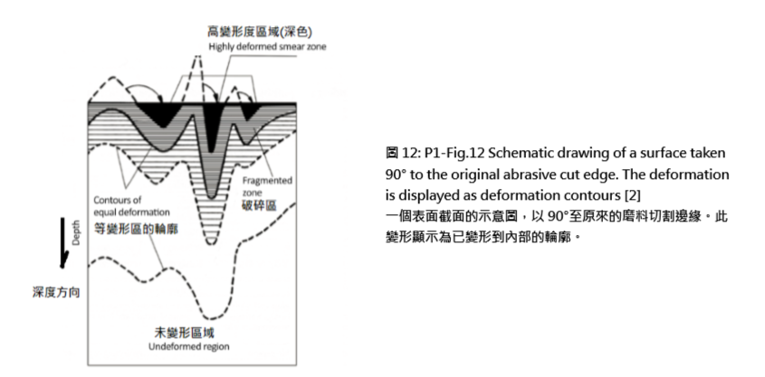
Regardless of the method used, abrasive sectioning of the sample produces a layer of material not representative of the true microstructure. The depth of the deformation is dependent on the sectioning technique and the skill of the operator. A schematic drawing of the deformation is shown in P1-Fig.12. 不管用什麼方法,樣品表面的研磨切片產生一層不真實 的表面組織會干擾真的要觀察的表面。變形的深度取決 於切片技術和操作者的技能,變形的示意圖如P1-圖.12 所示。
The section illustrated in this figure is taken perpendicular to the original abrasive cut edge, where the most deformation is located at the edge, decreasing in severity with movement away from the edge. In metallographic sample preparation, the deformed and fragmented zones must be removed in order to reach the region representing the true microstructure, the un-deformed region. 在這個圖中所示的部分是垂直於原來的磨料切割邊緣, 其中最變形位於邊緣,減少在嚴重程度與遠離邊緣的運 動。在金相樣品製備中,變形和破碎的區域必須被刪除, 以達到代表真實的微觀結構的區域,非變形區域。
In porous specimens, the deformation caused by sectioning appears as a distortion of the microstructure and on occasion, as a dandified layer, as was demonstrated in P1-Fig.4. The porosity network also presents preparation problems unique to PM, where the pores are filled with material smeared into the void spaces by the force of the blade into the specimen. During sample preparation, the aim of the next two steps in the process, grinding and polishing, is to remove all of the deformation in order to reveal the true microstructure. This is done in a series of abrasive steps where a sequence of finer abrasives is used to remove the existing deformation on the surface, while producing a thinner deformation zone. At the conclusion of the final polishing step, the prepared surface should represent the true microstructure. It is at this point where an accurate evaluation of the microstructure can be performed. 在多孔的樣品中,作為一個緻密化層的切片會造成變形 而呈現為一個扭曲的組織,如P1-圖.4中顯示(?原文 指的圖4,譯者認為是圖5)。孔隙網造成獨特的製備問 題,在粉末冶金品中,孔隙中填充的鑲埋材料會受到刀 片切割的力量使之擠入孔隙中。在樣品製備過程中,金 相加工過程的兩個步驟:研磨和拋光,是為了消除所有 的變形,以揭示樣品真正的微觀結構。
在一系列的研磨步驟,會用一個較細於上一級的磨料來 去除表面上的現有變形,而產生一個較薄的變形區。然 後,在最後的拋光步驟完成後,所製備的表面應代表真 正的微觀結構。這樣,顯微組織的準確評價,才可以進 行。■